
Aerospike’s Strong Consistency (SC) and rack awareness features allow construction of multi-site database clusters in which each site has a full copy of the data and all sites are perfectly synchronized.
This allows database operation to continue in the event of network partition between sites or site loss without loss of data.
The gold standard configuration is to use three data centres, as represented in the diagram below. In this diagram, each data centre corresponds to a physical rack and a replication factor of three has been chosen. As we have three racks, rack awareness will distribute the records so that there is exactly one copy of each record on each rack. Clients can be configured to read either from the master records, which are distributed uniformly across the three racks or from the local version, be it master or replica, using relaxed reads. In the diagram the relaxed read approach is shown, which optimises read latency.
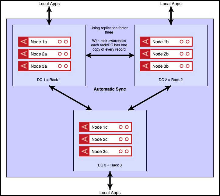
In the event of one of the three data centres becoming unavailable, there will be no data loss as each of the three data centres contains a full copy of the data. Aerospike’s resilience features will ensure that, in the event of failure, client applications automatically move to reading and writing from available data centres.
For those interested in the performance of such a configuration, my colleague Jagjeet Singh has written an excellent blog detailing results for a cluster that spans the east and west coasts of the USA.
An alternate arrangement is to run across two data centres as shown below. In this diagram, each data centre again corresponds to a physical rack and a replication factor of two has been chosen. As we have two racks, rack awareness will distribute the records so that there is exactly one copy of each record on each rack. For reasons explained below, we have an odd/even split across the two DCS. Only the red nodes are initially active. The green node is on standby and is not part of the cluster. Again, the clients are shown operating in ‘relaxed read’ mode where they have a ‘preferred’ rack.
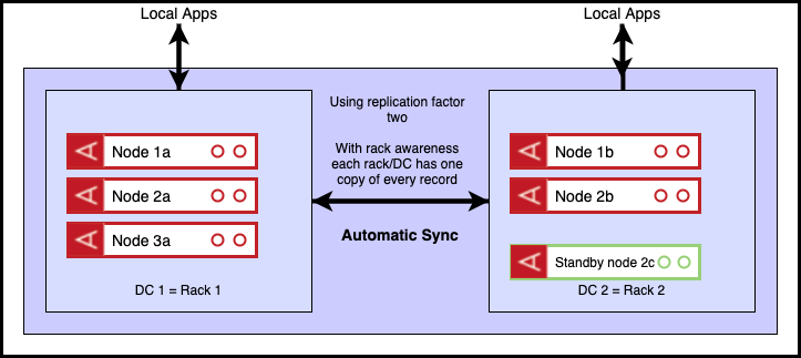
Once more, in the event of one of the two data centres becoming unavailable, there will be no data loss as each of the two data centres contains a full copy of the data.
Should the minority data centre (DC2) fail, client applications will automatically move to reading and writing from the available data centre (DC1).
Should the majority data centre (DC1) fail, the minority cluster (DC2) will block writes until a ‘roster’ command is issued, indicating that the minority cluster (DC2) should take over as the definitive master. The standby (green) node is also added to the cluster at this point for capacity purposes.
The odd/even arrangement is necessary as were the two data centres to contain equal number of nodes, our strong consistency rules would have the effect of 50% of partitions being active in each data centre which is unlikely to be the desired outcome.
Two trade-offs are being made here in order to guarantee consistency. The first is the need for potential operator intervention, and the second is the uneven balance of the two sides. Automation can be used to deal with the first, and a ‘spare’ node might well be considered a reasonable price to pay for consistency.
An alternative is available however, via a small change made in a recent server release – 5.2. It allows us to add a permanently quiesced node to the cluster. A quiesced node is one that does not master data, but may still participate in partition availability decisions. We can use such a node as a ‘tie-break node’, as shown in the arrangement below.
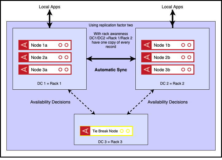
In the event of one of the DC1 or DC2 becoming unavailable, there will be no data loss as each of the two data centres contains a full copy of the data. If this event were a network partition, making DC1 unreachable from DC2 and DC3, the cluster will automatically reconfigure to serve all writes and reads from DC2 thanks to the extra vote from the tie break node, serving to make DC2+DC3 a majority cluster. Similar behaviour occurs if DC2 is unreachable from DC1 and DC3. Finally the unavailability of DC3 would have no consequence as DC1+DC2 forms a majority.
We have eliminated the need for operator intervention in the majority failure case in the above scenario as well as avoiding the need for a fully specified ‘spare’ node (needed previously to accommodate necessary migrations to ensure full replication of data). This is because our ‘tie break node’ has no capacity requirements associated with it – it is there solely for decision making purposes.
The trade-off is the need for a third data centre. It can be seen however that this still offers an advantage over the ‘gold standard’ in that we reduce our inventory by 1/3. An additional iteration might be to double the number of tie-breaker nodes in DC3. Although not strictly necessary this might assuage any concerns around single point of failure.
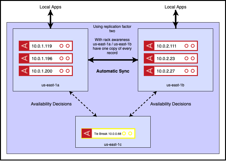
Let’s see how this works in practice. In the diagram below, I distribute my cluster across 3 AWS availability zones. The data nodes are in us-east-1a/b, with the tie breaker in us-east-1c.
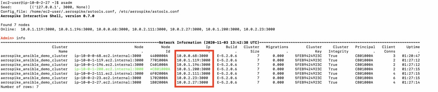
The Aerospike admin tool can be used to show cluster state. The IP addesses of each node are highlighted.
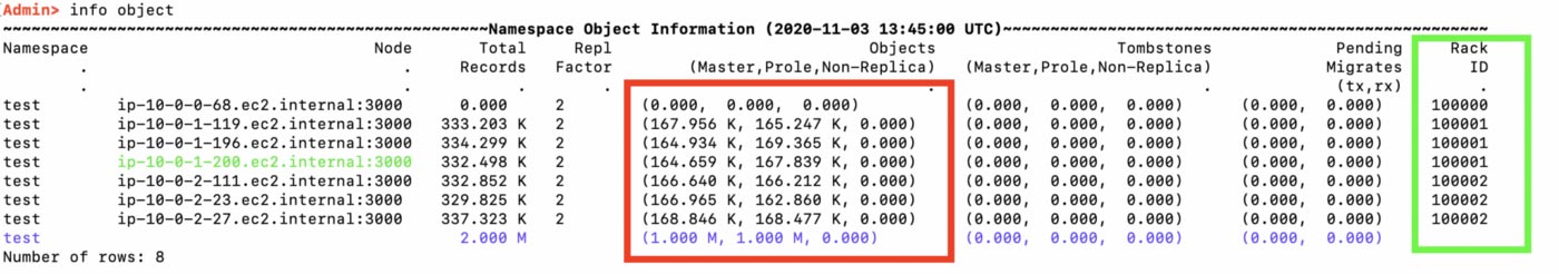
Next we add some data – 1m objects in this case and again, inspect state. We can see below (red highlight) that we have 1m master records, 1m replica records, and the green highlight shows us how our servers have been separated into three racks – corresponding to the availability zones. The tie-break node, 10.0.0.68, in us-east-1c, is in a rack of its own and is not managing any data.
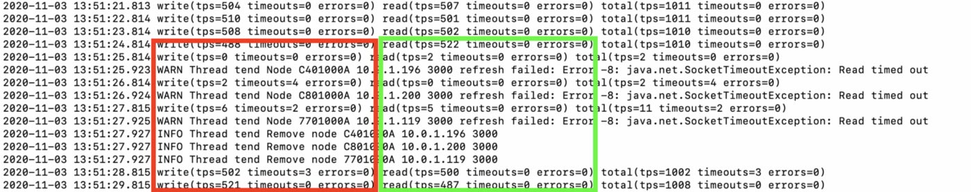
We can simulate a network partition by completely firewalling off us-east-1a. Let’s say we do this while we have active reads and writes taking place.The screenshot below shows this happening at approx 13:51:25. We can see that we get no errors on the read side (because replicas will be tried in the event of timeouts/fails) and some write timeouts (these are the in-flight writes at the time of the network partition). We also see (last 5 lines) the client removing the unavailable nodes from its internal node list and normal operation being resumed.
On the server side, we can see below that we lose all the nodes in rack 100001, corresponding to those with the 10.0.1.* addresses. The number of master records stays as expected (green highlight), while we need to create prole or replica records (blue highlight) to allow for the fact that immediately after the network partition we only have one copy of each record. This is seen in the migration statistics (purple highlight).
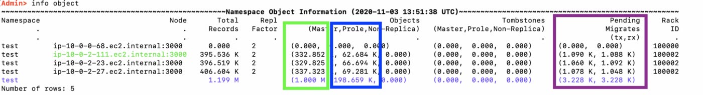
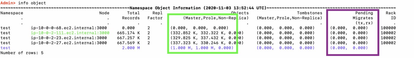
Once the migrations are complete (purple highlight), we have a full complement of master and prole (replica) objects (green highlight).
Conclusion
We can use the new tie-breaker capability to build fully resilient distributed Aerospike clusters, while minimising hardware usage.


